


1. Input voltage: DC 5V-36V
2. Output voltage: DC 1.25V-32V
3. Maximum output current: 5A (recommended for use within 4.5A)
4. Output power: Maximum 75W
5. Working temperature: -40~+85 degrees Celsius
6. Operating frequency: 180KHz
7. Conversion efficiency: up to 96%
8. Short circuit protection: Yes
9. Overtemperature protection: Yes (automatically shuts off output after overheating)

Self correction method:
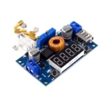
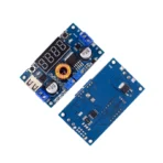
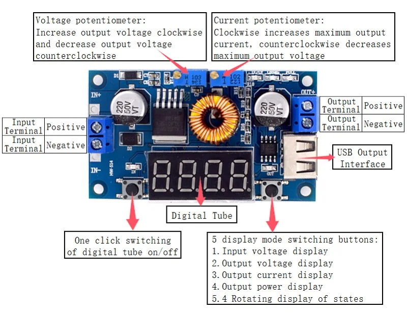
When the onboard digital meter displays the output voltage, press and hold the button on the right side for 2 seconds and then release it. The voltmeter and output voltage indicator light “OUT” will flash synchronously, entering the output voltage calibration mode; Similarly, when the voltmeter displays the input voltage, press and hold the button on the right side for 2 seconds and then release it. The voltmeter and input voltage indicator light “IN” will flash synchronously, entering the input voltage calibration mode; When the voltmeter displays the output current, press and hold the button on the right side for 2 seconds and then release it. The ammeter flashes and enters the output current calibration mode;
2. Tap the button on the right to increase the voltage (current) by 0.1V, and tap the button on the left to decrease the voltage (current) by 0.1V
After adjusting the voltage (current), press and hold the button on the right side for 2 seconds and then release it to exit the calibration mode. All parameter settings will automatically power off and save.
Special attention:
1. Be careful not to connect the positive and negative terminals of the input power supply in reverse, otherwise it may cause damage to the module.
2. When adjusting the voltage (current), follow the following method: When the module is not powered and not connected to a load, align the copper head of the blue potentiometer with the chest of the person, rotate the potentiometer counterclockwise to the bottom (more than 30 turns), hear a “click” sound, turn on the power, and use a multimeter to monitor the output voltage (current) of the module. Rotate the potentiometer clockwise to achieve the ideal voltage (current). It’s useless to rotate this potentiometer a few times in the initial stage.
3. If the traffic light and green light are on together when adjusting the voltage before use, which causes the module to be unable to adjust the output voltage normally, please rotate the current potentiometer to increase the output current until the red light is off and only the green light is on, and then rotate the voltage potentiometer to adjust the voltage.
4. Do not mix the input ground and output ground of the module together, as this will cause the current sampling resistor of the module to bypass, making it impossible for the module to adjust the output current, and it is easy to burn out the module when connected to a load.
5. The output terminal of the module has a current sampling resistor in series. When connected to a load, there will be a voltage drop of 0-0.2V, which is a normal phenomenon.
Attention: The USB port does not have a fixed output voltage of 5V. Please use it with caution to avoid damaging other items.

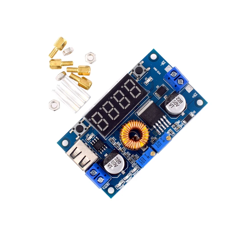
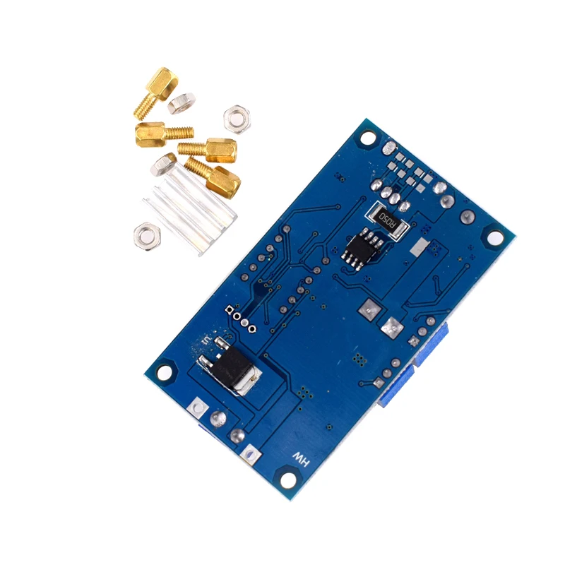
usage method:
1. Used as a common voltage reduction module with overcurrent protection capability
usage method:
(1) Press the button on the right to adjust the digital meter to the ‘Display Output Voltage’ interface, adjust the ‘Constant Voltage Potentiometer’ to achieve the desired output voltage value;
(2) Adjust the digital meter to the ‘Display Output Current’ interface and directly short-circuit the output terminal of the module (by finding a thick wire to short-circuit the output terminal). At this time, adjust the ‘Constant Current Potentiometer’ to make the current value on the digital meter reach the preset overcurrent protection value; (For example, if the current value displayed on the onboard ammeter is 4A, the maximum current of the module is limited to 4A, and the red indicator light will light up when the current reaches 4A.)
(3) Connect the load and work.
2. Used as a battery charger
Modules without constant current function cannot be used to charge batteries. Due to the large voltage difference between the depleted battery and the charger, the charging current is too high, causing battery damage. Therefore, constant current charging should be used for the battery at the beginning, and when it reaches a certain level of charging, it will automatically switch back to constant voltage charging.
usage method:
(1) Determine the float charging voltage and charging current of the battery; (If the parameters of the lithium battery are 3.7V/2200mAh, then the float charging voltage is 4.2V and the maximum charging current is 1C, which is 2200mAh)
(2) Under no-load conditions, adjust the digital meter of the module to the ‘Display Output Voltage’ interface and adjust the ‘Constant Voltage Potentiometer’ to achieve the floating charge voltage output voltage;
(3) Adjust the digital meter to the ‘Display Output Current’ interface and directly short-circuit the output terminal of the module (by finding a thick wire to short-circuit the output terminal). At this time, adjust the ‘Constant Current Potentiometer’ to make the current value on the digital meter reach the preset charging current value;
(4) The default factory charging current for switching from charging to lighting is 0.1 times the charging current; (The current of the battery gradually decreases during the charging process, gradually shifting from constant current charging to constant voltage charging. If the charging current is set to 1A, when the charging current is less than 0.1A, the blue light will turn off and the green light will turn on, indicating that the battery is fully charged.)
(5) Connect the battery and charge it.
(Steps 1, 2, 3, and 4 are: Connect the input terminal to the power supply, and the output terminal is unloaded without connecting the battery)
3. Used as an LED constant current driver module
(1) Determine the operating current and maximum operating voltage required to drive the LED;
(2) Under no-load conditions, adjust the digital meter to the ‘Display Output Voltage’ interface and adjust the ‘Constant Voltage Potentiometer’ to achieve the LED working voltage output voltage;
(3) Adjust the digital meter to the ‘Display Output Current’ interface and directly short-circuit the output terminal of the module (by finding a thick wire to short-circuit the output terminal). At this time, adjust the ‘Constant Current Potentiometer’ to make the current value on the digital meter reach the preset LED working current;
(4) Connect the LED and test the machine.
(Steps 1, 2, and 3 are: Input connected to power supply, output unloaded without LED light)
Note: This function is used to calibrate the display accuracy of voltage and current, not to adjust the output voltage and current values. This feature is designed to meet your higher precision requirements, and you only need to calibrate once to get accurate results across the entire range.