Custom Display Manufacturing in China: A Complete Guide to Sourcing Screens
Whether you are developing an IoT device, a medical instrument, or consumer electronics, the display is often the most critical
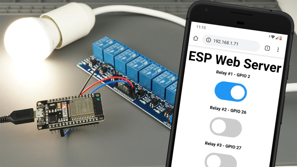
Control lights, fans, and other household devices from anywhere in the world using an ESP32 and a relay module. This comprehensive, step-by-step guide walks you through creating a secure web interface for safe remote control of AC appliances.*
This tutorial provides everything you need to know to safely control high-voltage AC appliances remotely using a low-cost ESP32 microcontroller and a relay module. We’ll build a secure web server that allows you to turn devices on and off from any web browser on your local network. Whether you’re starting a home automation project or learning about IoT device control, this guide covers the hardware, wiring, code, and crucial safety practices you must follow.
This project transforms your ESP32 into the brain of a remote control system. The ESP32 hosts a web page with toggle switches. When you click a switch, it sends a command to a relay module—an electronic switch—which physically connects or disconnects the high-voltage power to your appliance.
⚠️ CRITICAL SAFETY WARNING: You will be working with MAINS VOLTAGE (120V/230V), which is lethal and can cause serious injury, fire, or death if mishandled.
Do not proceed if you are unfamiliar, uncomfortable, or untrained in working with mains electricity.
Never wire the high-voltage side of the relay while the circuit is plugged in or powered.
Always enclose the final project in a proper electrical enclosure.
Double-check all connections with the power disconnected before applying voltage.
Consider practicing first with a low-voltage DC device (like a 12V lamp or fan) to understand the concepts safely.
A relay is an electrically operated switch. It allows the low-voltage, low-current signal from an ESP32 GPIO pin (3.3V) to safely control a separate, high-voltage, high-current circuit (like a 120V AC lamp).
Voltage Isolation: The core feature. The coil (control side) and the contacts (switching side) are magnetically linked but electrically isolated, protecting your ESP32 from high-voltage spikes.
Optocoupler (Recommended): Many modules include an additional optocoupler (or opto-isolator). This component uses light to transmit the control signal, creating an extra layer of electrical isolation and significantly boosting the protection for your microcontroller.
Channel Configurations: Modules come with 1, 2, 4, 8, or even 16 independent relays. Choose based on how many devices you need to control independently.
A standard 2-channel relay module has two distinct sides:
Low-Voltage Side (Control Side): Connects to the ESP32.
VCC / JD-VCC & GND: Powers the relay’s electromagnet.
IN1, IN2…: Input pins that receive the control signal from the ESP32‘s GPIOs.
High-Voltage Side (Switching Side): Connects to the AC appliance.
COM (Common): The central terminal where the incoming AC line is connected.
NO (Normally Open): The terminal that is open (disconnected from COM) when the relay is off. The circuit closes (power flows) when the relay is activated.
NC (Normally Closed): The terminal that is closed (connected to COM) when the relay is off. The circuit opens (power stops) when the relay is activated.
Choosing NO vs. NC:
Use Normally Open (NO) configuration for devices you turn on occasionally (e.g., a lamp, a fan). The default state (relay off) is “power off,” which is generally safer.
Use Normally Closed (NC) for devices that should stay on unless triggered (e.g., a security system siren that activates on a breach). This is less common in basic automation.
You will find a jumper cap connecting the VCC and JD-VCC pins on most modules.
Jumper ON: The relay coil draws power from the ESP32‘s 5V pin. This is simpler but provides less isolation.
Jumper OFF (Recommended for AC): You must provide a separate, isolated power supply (e.g., a 5V wall adapter) to the JD-VCC pin. This, combined with the optocoupler, provides full electrical isolation between the ESP32 and the high-voltage circuit, which is the safest practice for controlling AC mains.
Relay module (with optocoupler, 5V compatible)
Breadboard and jumper wires
AC power cord & plug
AC socket outlet or terminal block
Electrical enclosure
For initial testing: A low-voltage DC bulb/12V power supply is highly recommended to verify functionality safely.
*Follow this diagram for a single-channel setup. For more channels, connect additional relay IN pins to other ESP32 GPIOs.*
Here is how to connect the components:
| Relay Module Pin | Connects to ESP32 / Power | Notes |
|---|---|---|
| GND | GND | Common ground. |
| VCC | VIN (5V) or external 5V supply | Power for the module’s logic. |
| JD-VCC | External 5V supply (if jumper removed) | For isolated coil power. |
| IN1 | GPIO 26 | Control signal. Can use most GPIOs (e.g., 16, 17, 18). |
| COM | AC Line (Live/Hot Wire) | ⚠️ Handle with extreme care. |
| NO | To the Appliance (Load) | The switched AC line going to your lamp. |
| Appliance Other Wire | AC Neutral | Completes the AC circuit. |
Safety Steps for AC Wiring:
Unplug everything.
Connect the ESP32 and relay’s low-voltage side as per the table.
For the high-voltage side: Carefully connect the AC power cord’s Live (Hot) wire to the relay’s COM terminal. Connect the wire going to your appliance to the NO terminal.
Connect the appliance’s other wire and the AC power cord’s Neutral wire together securely (using a wire nut or terminal block).
Insulate all AC wire connections and secure them inside the enclosure before even thinking about plugging in the cord.
We will program the ESP32 to create a Wi-Fi access point or connect to your local network and host a web page with interactive buttons.
Open the Arduino IDE. Navigate to Sketch > Include Library > Manage Libraries… and install these two libraries:
ESPAsyncWebServer by me-no-dev
AsyncTCP by me-no-dev
These libraries enable the ESP32 to handle web requests efficiently without blocking its code.
The complete code (provided in the next section) performs several key functions. Here’s a breakdown of the critical parts you need to configure:
A. Network Configuration:
Replace the placeholder with your Wi-Fi credentials to have the ESP32 join your local network.
const char* ssid = "YOUR_WIFI_SSID";
const char* password = "YOUR_WIFI_PASSWORD";
B. Relay Configuration:
Define if your relay module is wired in Normally Open (true) or Normally Closed (false) mode.
#define RELAY_NO true
C. Defining Relays:
Set the number of relays and their corresponding GPIO pins. This example is set up for 2 relays.
#define NUM_RELAYS 2
int relayGPIOs[NUM_RELAYS] = {26, 27}; // GPIOs for Relay 1 & 2
Copy and paste the following code into your Arduino IDE. Remember to update the ssid, password, NUM_RELAYS, and relayGPIOs array to match your setup.
/*********
 * ESP32 Web Server for Relay Control
 * Based on original work by Rui Santos @ RandomNerdTutorials
 * Complete project details: https://RandomNerdTutorials.com/esp32-relay-module-ac-web-server/
 *********/

#include "WiFi.h"
#include "ESPAsyncWebServer.h"

// Set to TRUE for Normally Open relays, FALSE for Normally Closed
#define RELAY_NO true

// Define the number of relays and their GPIO pins
#define NUM_RELAYS 2
int relayGPIOs[NUM_RELAYS] = {26, 27}; // Modify pins here

// Your WiFi credentials
const char* ssid = "YOUR_WIFI_SSID";
const char* password = "YOUR_WIFI_PASSWORD";

AsyncWebServer server(80);

// HTML and CSS for the web interface (stored in PROGMEM to save RAM)
const char index_html[] PROGMEM = R"rawliteral(
<!DOCTYPE html>
<html>
<head>
    <title>ESP32 Relay Control</title>
    <meta name="viewport" content="width=device-width, initial-scale=1">
    <style>
        body { font-family: Arial; text-align: center; margin: 40px; }
        h2 { color: #2c3e50; }
        .switch { position: relative; display: inline-block; width: 80px; height: 44px; margin: 15px; }
        .switch input { opacity: 0; width: 0; height: 0; }
        .slider { position: absolute; cursor: pointer; top: 0; left: 0; right: 0; bottom: 0; background-color: #ccc; transition: .4s; border-radius: 34px; }
        .slider:before { position: absolute; content: ""; height: 36px; width: 36px; left: 4px; bottom: 4px; background-color: white; transition: .4s; border-radius: 50%; }
        input:checked + .slider { background-color: #2196F3; }
        input:checked + .slider:before { transform: translateX(36px); }
        .relay-label { font-size: 1.2em; margin-bottom: 5px; display: block; }
        .state { font-size: 1em; color: #7f8c8d; margin-top: 5px; }
    </style>
</head>
<body>
    <h2>ESP32 Relay Control Panel</h2>
    <p>Control your connected AC appliances remotely.</p>
    <div id="relayGrid">%BUTTONPLACEHOLDER%</div>
    <script>
        function toggleRelay(element) {
            const relayNum = element.id;
            const newState = element.checked ? 1 : 0;
            // Update visual state immediately for better UX
            document.getElementById(`state${relayNum}`).innerText = newState ? "ON" : "OFF";

            // Send the control command to the ESP32
            fetch(`/update?relay=${relayNum}&state=${newState}`)
                .then(response => {
                    if (!response.ok) {
                        // Revert toggle if the command failed
                        element.checked = !element.checked;
                        document.getElementById(`state${relayNum}`).innerText = element.checked ? "ON" : "OFF";
                        alert("Command failed. Check ESP32 connection.");
                    }
                });
        }
    </script>
</body>
</html>
)rawliteral";

// Processor function to dynamically insert relay buttons into the HTML
String processor(const String& var) {
    if (var == "BUTTONPLACEHOLDER") {
        String buttons = "";
        for (int i = 1; i <= NUM_RELAYS; i++) {
            int gpio = relayGPIOs[i - 1];
            String state = relayState(i);
            String stateText = (state == "checked") ? "ON" : "OFF"; // Logic depends on RELAY_NO
            buttons += String() +
                "<div class='relay-container'>" +
                "<span class='relay-label'>Relay #" + i + " (GPIO " + gpio + ")</span>" +
                "<label class='switch'>" +
                "<input type='checkbox' onchange='toggleRelay(this)' id='" + i + "' " + state + ">" +
                "<span class='slider'></span>" +
                "</label>" +
                "<div class='state' id='state" + i + "'>" + stateText + "</div>" +
                "</div>";
        }
        return buttons;
    }
    return String();
}

// Helper function to determine the initial checkbox state based on relay's physical state
String relayState(int relayNum) {
    int gpioState = digitalRead(relayGPIOs[relayNum - 1]);
    if (RELAY_NO) {
        // For NO: Relay is ACTIVE (device ON) when pin is LOW
        return (gpioState == LOW) ? "checked" : "";
    } else {
        // For NC: Relay is ACTIVE (device ON) when pin is HIGH
        return (gpioState == HIGH) ? "checked" : "";
    }
}

void setup() {
    Serial.begin(115200);

    // Initialize all relay GPIOs as outputs and set to a safe default state (OFF)
    for (int i = 0; i < NUM_RELAYS; i++) {
        pinMode(relayGPIOs[i], OUTPUT);
        if (RELAY_NO) {
            digitalWrite(relayGPIOs[i], HIGH); // HIGH means OFF for Normally Open
        } else {
            digitalWrite(relayGPIOs[i], LOW); // LOW means OFF for Normally Closed
        }
    }

    // Connect to Wi-Fi
    WiFi.begin(ssid, password);
    Serial.print("Connecting to WiFi");
    while (WiFi.status() != WL_CONNECTED) {
        delay(500);
        Serial.print(".");
    }
    Serial.println("\nConnected! IP Address: " + WiFi.localIP().toString());

    // Configure web server routes
    // Serve the main control page
    server.on("/", HTTP_GET, [](AsyncWebServerRequest* request) {
        request->send_P(200, "text/html", index_html, processor);
    });

    // Handle the control command (e.g., /update?relay=1&state=1)
    server.on("/update", HTTP_GET, [](AsyncWebServerRequest* request) {
        String inputMessage;
        String inputParam;

        if (request->hasParam("relay") && request->hasParam("state")) {
            int relayIndex = request->getParam("relay")->value().toInt() - 1; // Convert to zero-based index
            int desiredState = request->getParam("state")->value().toInt();

            // Validate the relay index
            if (relayIndex >= 0 && relayIndex < NUM_RELAYS) {
                if (RELAY_NO) {
                    // For NO: LOW activates the relay (turns device ON)
                    digitalWrite(relayGPIOs[relayIndex], desiredState ? LOW : HIGH);
                } else {
                    // For NC: HIGH activates the relay (turns device ON)
                    digitalWrite(relayGPIOs[relayIndex], desiredState ? HIGH : LOW);
                }
                Serial.printf("Relay %d set to %s\n", relayIndex + 1, desiredState ? "ON" : "OFF");
                request->send(200, "text/plain", "OK");
            } else {
                request->send(400, "text/plain", "Invalid Relay");
            }
        } else {
            request->send(400, "text/plain", "Missing Parameters");
        }
    });

    // Start the web server
    server.begin();
    Serial.println("HTTP server started");
}

void loop() {
    // The AsyncWebServer handles requests in the background, so no code is needed here.
}
Select your ESP32 board (e.g., DOIT ESP32 DevKit V1) and the correct COM port in the Arduino IDE.
Click Upload.
Open the Serial Monitor (Tools > Serial Monitor) at a baud rate of 115200.
You should see the ESP32 connect to Wi-Fi and print its IP address (e.g., 192.168.1.100).
On any device connected to the same Wi-Fi network, open a browser and go to that IP address. You should see your control panel with toggle switches for each relay. Test the control with your appliance disconnected from AC power first.
Secure Access: The current server is on your local network only. For remote access, research safe methods like a VPN (e.g., WireGuard on a Raspberry Pi) or a cloud-based IoT platform like ESPHome or Blynk, which handle security more robustly than simple port forwarding.
Adding Schedules & Automation: Integrate a time library (like NTPClient) to turn relays on/off based on the time of day.
Voice Control: Use the web server as a backend for platforms like Home Assistant or OpenHAB to enable control via Amazon Alexa or Google Home.
Sensor Integration: Combine with a temperature sensor (DHT22) to create a thermostat, or with a motion sensor (PIR) to activate lights.
| Problem | Possible Cause | Solution |
|---|---|---|
| Relay doesn’t switch. | Wrong GPIO/wiring; Power jumper issue. | Check IN pin connection; ensure module is powered (LED on). Check RELAY_NO setting in code. |
| Web page won’t load. | ESP32 not connected to Wi-Fi; Wrong IP. | Check Serial Monitor for connection status and IP. Ensure device is on the same network. |
| Relay clicks but appliance doesn’t power. | Faulty AC wiring; Appliance issue. | Unplug AC! Verify wiring at COM and NO terminals with a multimeter’s continuity test. |
| ESP32 resets when relay switches. | Insufficient power/current. | Use a separate 5V power supply for the JD-VCC pin (remove jumper). Ensure your ESP32 USB cable is data-capable. |
| Web control is delayed/unreliable. | Weak Wi-Fi signal. | Ensure the ESP32 has good signal strength. Consider using the ESPAsyncWiFiManager library for easier network setup. |
You have now successfully built a secure, remote-controlled power switch using an ESP32. This project forms the foundation for countless home automation and IoT applications. The key takeaways are the paramount importance of safety when dealing with AC voltage and the flexibility of the ESP32 as a web server.
For your next steps, consider adding physical safety features like a master power switch on the enclosure and exploring over-the-air (OTA) updates to program your ESP32 wirelessly. Always prioritize creating a robust and safe final product over speedy completion.
======================================
No account yet?
Create an Account