ESP32 Dev Board vs Custom PCB: When to Switch
Every ESP32 product starts on a dev board. That is the right way to start — you get a working

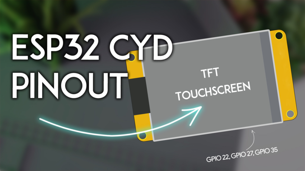
The ESP32-2432S028R, affectionately dubbed the Cheap Yellow Display (CYD) within the maker community, represents a significant leap in accessible IoT prototyping. This all-in-one development board integrates a powerful ESP32-WROOM-32 module with a vibrant 2.8-inch TFT touchscreen LCD, creating a perfect foundation for building interactive graphical user interfaces (GUIs) without the hassle of wiring separate components. Its integrated features—including a microSD card interface, RGB LED, light sensor (LDR), and accessible GPIOs—make it a uniquely practical solution for smart home dashboards, industrial controllers, and data visualization projects.
However, its integrated nature means many GPIO pins are dedicated to internal functions. This comprehensive pinout guide and resource explains not only what each pin does but also how to effectively utilize the available resources for your custom peripherals, ensuring you can plan and execute successful projects with the CYD.
The TFT display communicates via the ESP32's HSPI (SPI1) bus. Correct configuration in the TFT_eSPI library's User_Setup.h file is crucial. Note that GPIO 21, while listed as the backlight control, is often hardwired to be always on in many board revisions.
| SPI Function | GPIO Pin | Library Variable | Notes |
|---|---|---|---|
| MISO | GPIO 12 | TFT_MISO |
Master In, Slave Out |
| MOSI | GPIO 13 | TFT_MOSI |
Master Out, Slave In |
| SCLK | GPIO 14 | TFT_SCLK |
Serial Clock |
| Chip Select (CS) | GPIO 15 | TFT_CS |
Display enable pin |
| Data/Command (DC) | GPIO 2 | TFT_DC |
Differentiates data vs. command |
| Reset (RST) | -1 | TFT_RST |
Often tied to board's reset; use -1 |
| Backlight | GPIO 21 | TFT_BL |
Active LOW; may be non-controllable |
The resistive touchscreen uses the XPT2046 controller on the VSPI (SPI2) bus. For reliable touch functionality, ensure no other peripherals conflict with these pins.
| Touch Function | GPIO Pin | Common Variable |
|---|---|---|
| Interrupt (IRQ) | GPIO 36 | XPT2046_IRQ |
| MOSI | GPIO 32 | XPT2046_MOSI |
| MISO | GPIO 39 | XPT2046_MISO |
| Clock (CLK) | GPIO 25 | XPT2046_CLK |
| Chip Select (CS) | GPIO 33 | XPT2046_CS |
Pro Tip: For best performance with the TFT_eSPI library, use the community-modified branch that supports dual SPI buses, allowing independent and optimized management of the display and touch controller.
The microSD card shares the VSPI bus with the touchscreen but uses a separate Chip Select line. This allows both peripherals to coexist, though communication cannot happen simultaneously.
| SD Card Function | GPIO Pin |
|---|---|
| MISO | GPIO 19 |
| MOSI | GPIO 23 |
| SCK | GPIO 18 |
| Chip Select (CS) | GPIO 5 |
RGB LED: This surface-mount LED is active-LOW (set pin LOW to turn ON).
Red: GPIO 4
Green: GPIO 16
Blue: GPIO 17
Light Dependent Resistor (LDR): Connected to GPIO 34 (an analog input-capable pin). Use analogRead() to measure ambient light for auto-brightness features.
Speaker Connector: The 2-pin JST port is driven by GPIO 26. Use PWM audio libraries or simple tone generation.
Buttons: BOOT is tied to GPIO 0. RST is connected to the ESP32's enable pin.
This is the most critical section for project planning. While the ESP32 has many pins, the CYD's design pre-assigns most. Here is a realistic analysis of your free GPIOs.
These headers provide primary access to free pins, but with important caveats.
P3 Connector Pins:
GPIO 35: A free, input-only pin. Excellent for reading sensors, buttons, or digital signals. It cannot be used as an output.
GPIO 22: A free, versatile GPIO. Crucially, this is one of the ESP32's default I2C SCL pins.
GPIO 21: NOT FREE. This pin controls the display backlight. It will be held in a fixed state while the display is on.
CN1 Connector Pins:
GPIO 27: A free, versatile GPIO.
GPIO 22: The same pin as on P3, available here for convenience.
3.3V & GND: Provide power to external sensors.
You cannot use the default I2C pins (GPIO 21=SDA, GPIO 22=SCL) because GPIO 21 is occupied. The solution is to define a custom I2C bus using the free pins on CN1.
#include <Wire.h>
#define CUSTOM_SDA 27 // Use GPIO 27 on CN1
#define CUSTOM_SCL 22 // Use GPIO 22 on CN1/ P3

void setup() {
  Wire.begin(CUSTOM_SDA, CUSTOM_SCL); // Start I2C on custom pins
  // Now scan for I2C devices (sensors, RTC, etc.)
}
Community-Verified Application: Users have successfully connected BME280, AHT10, HTU21D temperature/humidity sensors and DS18B20 (OneWire, using GPIO 27) to these pins, creating compact weather stations and environmental monitors.
The P1 connector provides GPIO 1 (TX) and GPIO 3 (RX). These are directly connected to the onboard CH340 USB-to-serial converter.
Primary Use: For connecting a secondary GPS module (like NEO-6M/8M). You must use a SoftwareSerial or HardwareSerial on different pins (e.g., GPIO 27 for RX, GPIO 22 for TX) to avoid conflict with USB communication.
Warning: As noted by many users, using P1 for other serial peripherals often interferes with programming and serial debugging. It is not generally recommended for beginner projects.
After accounting for all integrated functions, you have three primary GPIOs for external components:
GPIO 35 (Input Only) – Read switches, analog sensors (via ADC), or digital inputs.
GPIO 22 (Input/Output) – Perfect for I2C SCL or general-purpose use.
GPIO 27 (Input/Output) – Ideal for I2C SDA, OneWire, or a simple output.
This configuration makes the CYD ideal for focused applications like sensor hubs with displays, IoT control panels, or smart clocks, rather than projects requiring dozens of outputs like large robotics.
Board Definition: In Arduino IDE or PlatformIO, select "ESP32 Dev Module."
TFT_eSPI Library: This is essential. After installing, navigate to its library folder and configure the User_Setup.h file. Select the correct driver (typically ILI9341_DRIVER) and enter the pin definitions from the table above. Comment out unused drivers to save memory.
Touch Calibration: Use the TFT_eSPI example "TouchCalibrate" to generate accurate calibration constants for your specific screen.
"Failed to initialize SD card": Ensure the microSD card is formatted as FAT32 (not exFAT). Check that the SD_CS pin (GPIO 5) is correctly defined.
Intermittent Touch or Display Glitches: This is often a power issue. The CYD can draw significant current, especially with a bright screen and active WiFi. Use a 5V/2A power supply connected via the board's USB-C port. Avoid powering solely from a weak computer USB port when using all features.
Unable to Upload Code (CH340 Driver): On Windows, you may need to install the CH340 USB driver manually. Mac and Linux typically handle it automatically.
Given its pin constraints, the CYD excels at these applications:
WiFi-Enabled Sensor Display: Connect a BME280 (via I2C on GPIO 22/27) and display real-time temperature/pressure/humidity graphs, posting data to MQTT.
Smart Home Control Panel: Use the touchscreen as an interface to control lights or relays via MQTT or HTTP. The RGB LED provides clear status feedback.
Internet Radio/Audio Player: Use the speaker output with an audio shield (connected via I2C) and the microSD for storing files.
The ESP32 Cheap Yellow Display strikes a remarkable balance between integrated convenience and programmability. While its available GPIOs are limited, strategic use of the CN1 connector for a custom I2C bus and understanding the role of each pin unlocks its true potential. By following this pinout guide, you can avoid common pitfalls and develop efficient, reliable projects that leverage its excellent touchscreen display as the centerpiece of your IoT innovation.
Ready to start coding? Begin with the basic TFT_eSPI examples to test your display and touchscreen, then integrate sensor libraries using the custom I2C pins outlined above. The community is active—share your creations and solutions to help the next maker
======================================
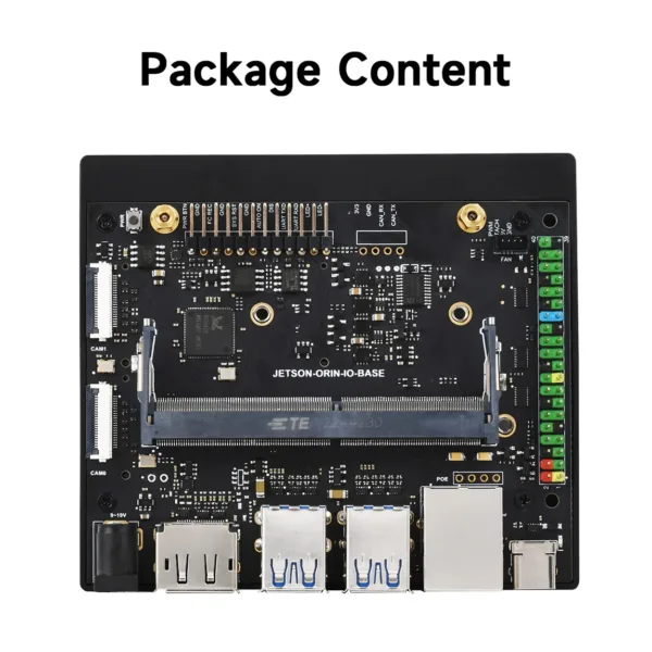 Jetson Orin Nano/NX Development Board Based on Jetson Orin Nano and Jetson Orin NX Module, 5× USB Ports
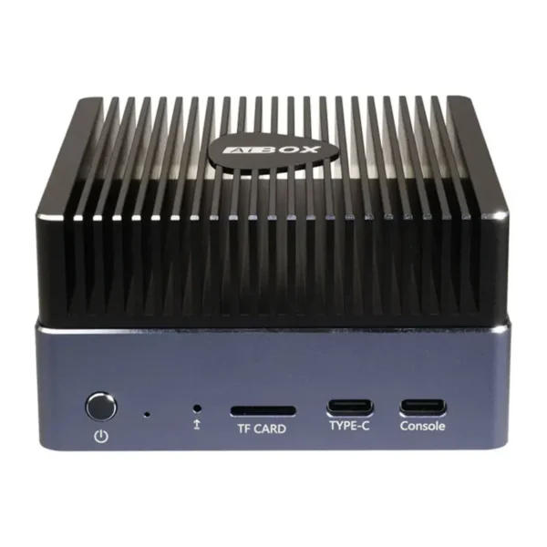 FIREFLY AIBOX-3588 Rockchip RK3588 for IoT Automation Machine Vision 5G AI Edge Computer Embedded PC
$310.80 – $685.90Price range: $310.80 through $685.90
FIREFLY AIBOX-3588 Rockchip RK3588 for IoT Automation Machine Vision 5G AI Edge Computer Embedded PC
$310.80 – $685.90Price range: $310.80 through $685.90
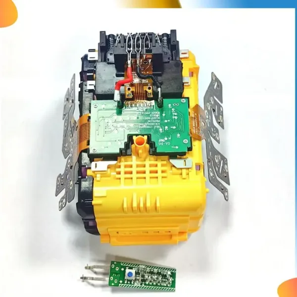 B48A 21700 Lithium Battery Protection Board For Dewalt 20V 60V Battery Lithium Battery Charging Protection Circuit Board
$18.90
B48A 21700 Lithium Battery Protection Board For Dewalt 20V 60V Battery Lithium Battery Charging Protection Circuit Board
$18.90
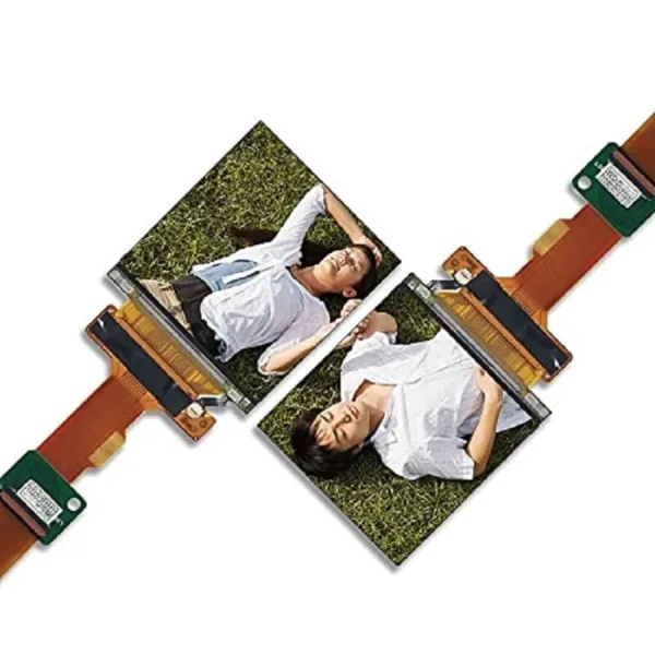 120Hz SLS029B3SX02 2.9 inch 1440*1440 2k Dual Square LCD Displays For VR Headset HMD Panel DP to MIPI Driver Controller Board
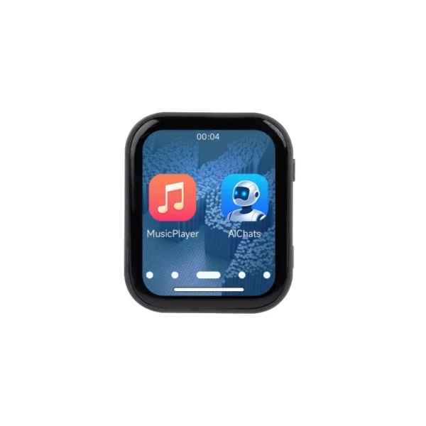 ESP32-S3 1.83 inch Touch Display Development Board, 240 × 284, Onboard Audio Codec Chip, Built-in Microphones And Speaker
$20.90 – $21.90Price range: $20.90 through $21.90
ESP32-S3 1.83 inch Touch Display Development Board, 240 × 284, Onboard Audio Codec Chip, Built-in Microphones And Speaker
$20.90 – $21.90Price range: $20.90 through $21.90
Every ESP32 product starts on a dev board. That is the right way to start — you get a working
Everyone talks about PCB layout, but the schematic is where most of the expensive mistakes actually happen. A layout error
esp32 pcb certification is one of the few parts of hardware development where the cost of getting it wrong is
An ESP32 iot board design is a system problem wearing a PCB costume. It has to sense something, power itself,
The ESP32-WROOM is probably the most common ESP32 module in the world. It is cheap, well-documented, and appears in thousands
The ESP32-S3 is the part people reach for when their product needs more than the classic ESP32 can give: native
No account yet?
Create an Account