


- High-concerned chemical: None
- is_customized: Yes
- Application: Computer
- Type: Module
- Brand Name: NoEnName_Null
- Origin: Mainland China
- Condition: New
Product Introduction
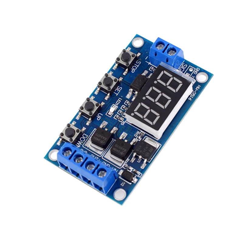
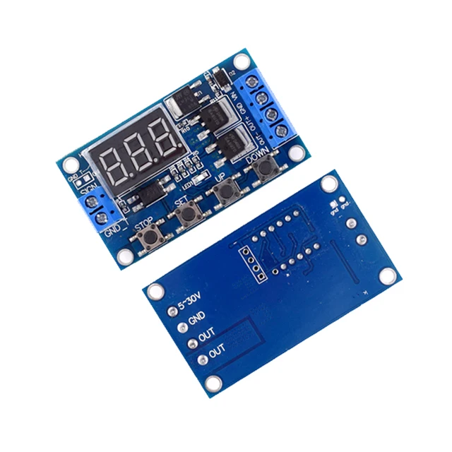
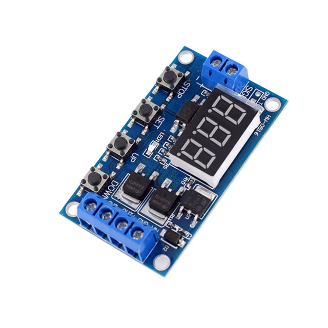
1. Adopting dual MOS parallel active output, the internal resistance is lower, the current is higher, and the power is strong. At room temperature, it is 15A and 400W, which meets the needs of most devices
2. Wide voltage, supports PWM
3. Able to control high-power devices
Product parameters
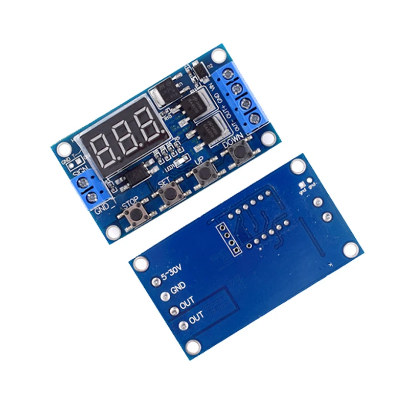
1: Working voltage: DC 5V –36V
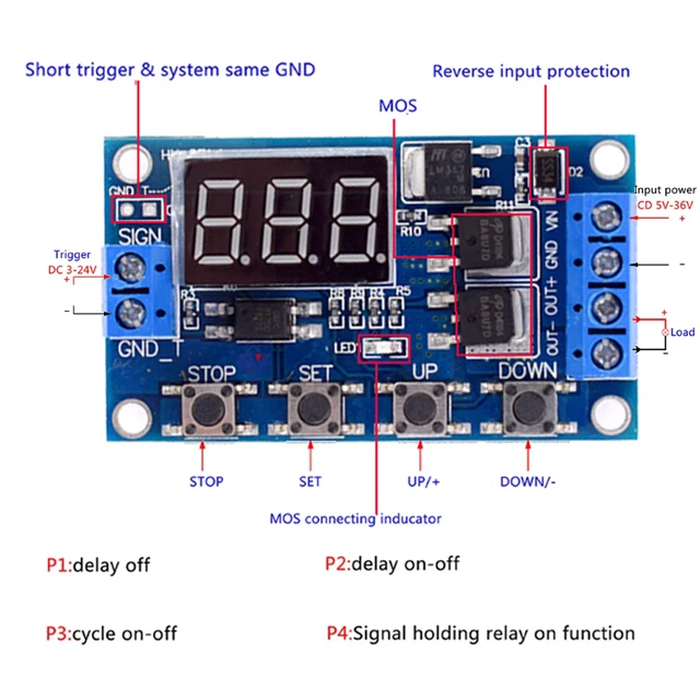
2: Trigger signal source: digital high and low levels (DC3.3V-20V), signal ground and system ground are not common to improve the anti-interference ability of the system (can also be self shorted to common ground)
3: Output capability: DC 5V-36V, continuous current 15A at room temperature, power 400W! Under auxiliary heat dissipation conditions, the maximum current can reach 30A
4: Static current: 15mA
5: Service life: unlimited switching; Working temperature: -40-85 ℃; Size: 6.0 * 3.4 * 1.2cm
6: Equipped with optocoupler isolation to enhance anti-interference ability, industrial grade circuit board, set parameters to be permanently remembered after power failure.
Working mode:
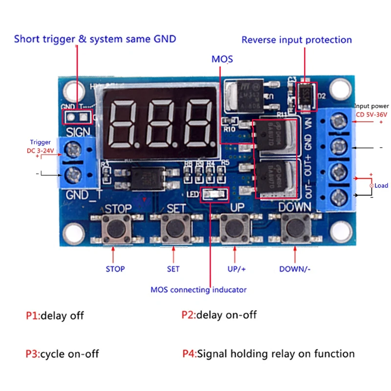
P1 mode: After the signal is triggered, the relay conducts for OP time and then disconnects; During the OP time, perform the following operations
P1.1: Signal triggered again is invalid
P1.2: Signal triggers again and restarts timing
P1.3: Signal triggers reset again, relay disconnects, and timing stops;
P-2: Give a trigger signal, disconnect the relay after CL time, conduct the relay for OP time, and disconnect the relay after timing is completed;
P3.1: Give a trigger signal, after the relay conducts OP time, the relay disconnects CL time, and then repeat the above actions. Within the cycle, give the signal again, the relay disconnects, and the timer stops; The number of loops (LOP) can be set;
P3.2: After power on, there is no need to trigger a signal. The relay conducts for OP time and disconnects for CL time, and the above actions are repeated; The number of loops (LOP) can be set;
P-4: If there is a trigger signal, the timer will be reset and the relay will remain conductive; When the signal disappears, disconnect the relay after timing OP; During the timing period, if there is a signal again, the timing will be reset to zero.
Timing range:
0.1 seconds (minimum)~999 minutes (maximum) continuously adjustable
How to choose a timing range:
After setting the parameter values on the mode selection interface, short press the STOP button to select the timing range;
XXX. The decimal point is in units, and the timing range is 1 second to 999 seconds
XX. The decimal point of X is in ten places, and the timing range is 0.1 seconds to 99.9 seconds
X. X.X. decimal point fully lit, timing range: 1 minute to 999 minutes
For example, if you want to set the OP to 3.2 seconds, move the decimal point to ten and the digital display will show 03.2
Parameter description: OP conduction time, CL disconnection time, LOP cycle times (1-999 times, “—” represents infinite cycles)
These parameters are independent of each other, but they are shared among different modes. For example, in P1.1, the conduction time OP is set to 5 seconds. If the user wants to switch to P1.2 mode, when entering P1.2 to set the corresponding parameters, the OP will also be 5 seconds;
Short press the SET button on the main interface (display 000) to display OP (CL, LOP) and the corresponding time XXX;
If there is only OP time in the mode (such as mode P1.1, P1.2, P1.3), pressing the SET key briefly will only display OP and corresponding time;
If there are OP, CL, LOP in the mode (such as mode P3.1, P3.2), short pressing the SET key will display OP and corresponding time, CL and corresponding time, LOP and corresponding number of times;
After setting the mode, you can easily view the parameters set in the current mode by short pressing the SET key on the main interface, which is very convenient!
Set parameters:
Firstly, determine the working mode of the relay;
2. According to the working mode of the relay, on the main interface (when the module is powered on, it will flash the current working mode (default P1.1 mode), and then enter the main interface), press and hold the SET button for 2 seconds and then release it to enter the mode selection interface. Short press the UP and DOWN buttons to select the mode to be set (P1.1~P-4);
3. After selecting the mode to be set (e.g. P3.2), press the SET key briefly to set the corresponding parameters. At this time, the parameters to be set will flash (OP conduction time, CL disconnection time, LOP cycle times (“—” represents infinite cycles)). Adjust the parameter values through UP and DOWN, and support long press (quick increase or decrease) and short press (increase or decrease by 1 unit); After setting the parameter values, short press the STOP key to select the decimal point position and choose the timing range (corresponding time from 0.1 seconds to 999 minutes); Short press the SET key to set the next parameter for the current mode, the process is the same as above;
After setting the parameters for the selected mode, press and hold the SET button for 2 seconds before releasing it. The currently set mode will flash and then return to the main interface. Setting the parameters is successful, very simple!
Main interface: When the relay is not working, it displays “000” (without a decimal point). When the relay is working, it has a decimal point, which is very clear!
Mode selection interface: Press and hold the SET key to enter. After setting is complete, press and hold the SET key to exit and return to the main interface. It’s very simple!
Relay enable mode:
1. ON: The relay is allowed to conduct during the OP conduction time;
2. OFF: The relay is prohibited from conducting and remains in a closed state;
Short press the STOP button on the main interface to switch between ON and OFF. The current state will flash, and then return to the main interface. (This function is an emergency stop function, a relay that can be opened and closed with one click)
Sleep mode:
1. C-P sleep mode: Within five minutes, if there is no operation, the digital display will automatically turn off and the program will run normally;
2. O-d normal mode: The digital display is always on;
Press and hold the STOP button for 2 seconds, then release it to switch between C-P and O-d states. The current state will flash, and then return to the main interface.
be careful:
1. The power supply voltage of the module should not exceed the maximum value that the module can withstand, otherwise it may damage the module.
2. Pay attention to wiring according to the diagram and do not make mistakes.
3. This document only represents the product parameters at the time of editing, and any changes in the future will not be notified separately.
4. The module is an active live output, and the voltage at the output terminal (load terminal) is equal to the voltage at the input terminal (DC 5V –36V).
5. DC.+ The ‘+’ poles of the load are inherently short circuited internally, but the ‘DC -‘ poles of the load cannot be short circuited during use, otherwise the load will not be able to be controlled to turn on and off, which is equivalent to the load being constantly powered on.