

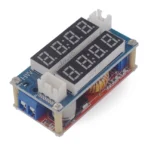

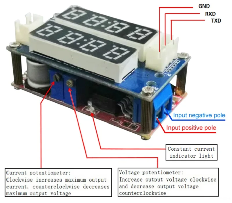
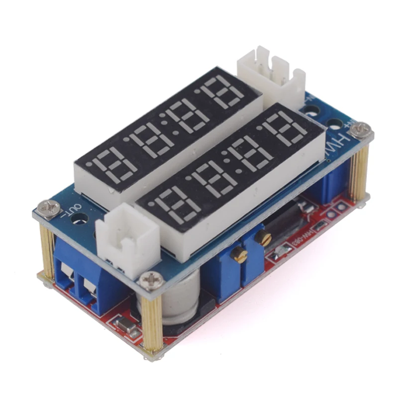
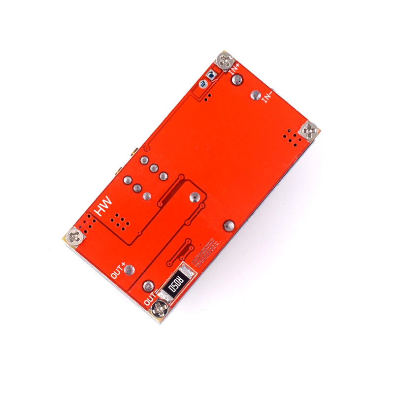
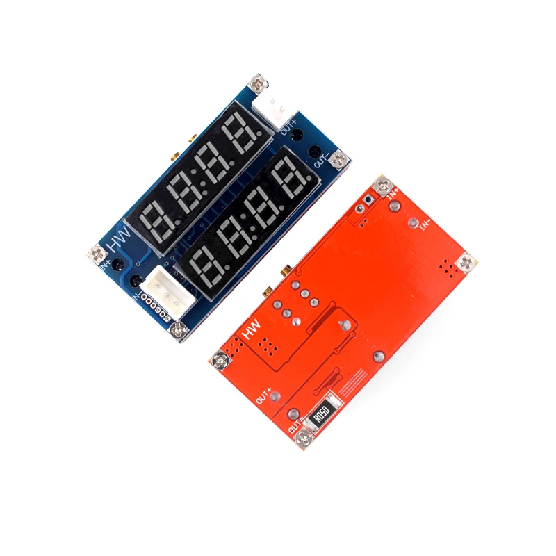
This module is an adjustable voltage reduction module with an LED digital tube, which can achieve real-time monitoring of output voltage and current. The output voltage and output current can be changed by adjusting the blue adjustable resistor on the module (refer to the functional diagram below for specific instructions). The input and output voltage difference is 1V.
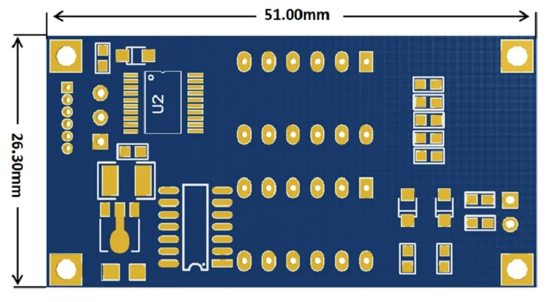
Product parameters:
1. Input voltage: DC5V-32V;
2. Output voltage: adjustable from DC0.8-30V;
3. Conversion efficiency: maximum 96%;
4. Output current: Maximum output current of 5A, adjustable;
5. Output power: maximum 75W;
Special attention:
1. Pay attention to wiring according to the diagram and do not make mistakes.
2. The positive and negative terminals of the input terminal cannot be reversed, otherwise the module will be directly burned out;
3. The maximum input voltage and maximum output current cannot be met simultaneously. Long term use should not be subjected to high voltage, high current, or hot plugging, and attention should be paid to strengthening heat dissipation;
4. The maximum output power is 75W, which is a limiting condition. Please leave some margin for use; When using this module with a power output exceeding 3A or 35W, please strengthen the heat dissipation;
5. When used as a voltage reduction module, the input voltage is greater than the output voltage;
6. If the digital display is incomplete or abnormal, check whether the copper pillar is installed properly, tighten the screws around the product, and connect the upper and lower plates.
Communication protocol description:
1. This module has the function of communicating with computers. Can facilitate computer reading of module current and voltage data;
2. As the output of this module is TTL level, to achieve communication with the computer, the module can be connected to the computer through a USB to TTL serial port module.
3. The communication protocol is as follows:
Baud rate: 9600 Bps
BB CC ADDR 00 XX XX CRC (current return command)
BB CC ADDR 01 XX XX CRC (Voltage Return Command)
of which
BB CC is the frame header (2 bytes)
ADDR is the module address (1 byte)
00 is the current reading command (1 byte)
01 is the command to read voltage (1 byte)
XX XX arbitrary value (2 bytes)
CRC Check (1 byte)
function characteristics:
1. It can be used as a common voltage reduction module with overcurrent protection capability;
2. Can be used as a battery or battery charger;
3. Can be used as a high-power LED constant current drive module;
4. It has two modes: constant current and constant voltage, and an indicator light to indicate which mode it is currently in;
When used as a lithium battery charger, the float charging voltage and charging current can be set, and there is an indicator light to indicate whether it is charging or fully charged;
6. It has a current limiting protection function, which will not burn out the module even if the output is short circuited.
Application scope:
1. Used as a common voltage reduction module with overcurrent protection capability
usage method:
(1) After power on, adjust the voltage potentiometer to make the output voltage reach the ideal voltage;
⑵ Measure the output short-circuit current with a multimeter in 10A current mode (simply connect the two probes to the output terminal), and adjust the current potentiometer to achieve the predetermined overcurrent protection value for the output current. (For example, if the current value displayed on the multimeter is 4A, then when you use the module, the high current can only reach 4A. When the current reaches 4A, the red constant current indicator light will turn on, otherwise the indicator light will turn off.)
Attention: When used in this state, due to the 0.05 ohm current sampling resistor at the output terminal, there will be a voltage drop of 0-0.3V when connected to the load, which is a normal phenomenon! This voltage drop is not caused by your load, but by the sampling resistor.
2. Used as a battery charger
Modules without constant current function cannot be used to charge batteries. Due to the large voltage difference between the depleted battery and the charger, the charging current is too high, causing battery damage. Therefore, constant current charging should be used for the battery at the beginning, and when it reaches a certain level of charging, it will automatically switch back to constant voltage charging.
usage method:
⑴ Determine the float charging voltage and charging current of the battery you need to charge; If the parameters of the lithium battery are 3.7V/2200mAh, then the float charging voltage is 4.2V and the maximum charging current is 1C, which is 2200mAh;
Under no-load conditions, measure the output voltage with a multimeter and adjust the voltage potentiometer to achieve the floating charge voltage; If charging a 3.7V lithium battery, adjust the output voltage to 4.2V;
Measure the output short-circuit current with a multimeter in 10A current mode (simply connect the two probes to the output terminal), and adjust the current potentiometer to achieve the predetermined charging current value;
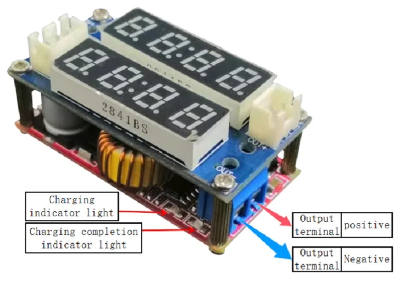
⑷ The default charging to light current is 0.1 times the charging current when it leaves the factory; (The current of the battery gradually decreases during the charging process, gradually shifting from constant current charging to constant voltage charging. If the charging current is set to 1A, when the charging current is less than 0.1A, the red charging indicator light will turn off and the red fully charged indicator light will turn on, indicating that the battery is fully charged.);
⑸ Connect the battery and charge it.
Attention: Steps ⑴ ⑵ ⑶ ⑷ are: Connect the input terminal to the power supply, and do not connect the output terminal to the battery when unloaded.
3. Used as a high-power LED constant current driver module
⑴ Determine the operating current and voltage required to drive the LED;
Under no-load conditions, measure the output voltage with a multimeter and adjust the voltage potentiometer to reach the high operating voltage of the LED;
Measure the output short-circuit current with a multimeter in 10A current mode, and adjust the current potentiometer to achieve the predetermined LED working current;
Connect the LED and test the machine.
Attention: Steps ⑴, ⑵, and ③ are: Connect the input terminal to the power supply, and do not connect the output terminal to the LED light when there is no load.