

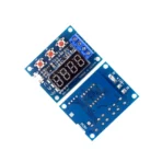

- High-concerned chemical: None
- Package: DIP
- is_customized: Yes
- Application: Computer
- Type: Module
- Brand Name: NoEnName_Null
- Origin: Mainland China
- Condition: New
- Model Number: ZB2L3 Module
Product Introduction
Power supply voltage: DC 4.5-6V (micro USB interface)
Working current: not exceeding 70mA
Discharge voltage: DC 1.00V-15.00V resolution 0.01V
Termination voltage range: 0.5-11.0V
Support current passing: maximum 3.000A resolution 0.001A
Maximum voltage measurement error: 1%+0.02V
Maximum error in current measurement: 1.2%+-0.002A
Maximum battery capacity range: 9999Ah (1Ah=1000mAh). Larger values are switched by decimal point shift, and when it is below 10Ah, it is displayed as X XXX , If it reaches 10Ah or above, it will be displayed as XX XX, and so on.


Attention:
1. In order to improve the accuracy of voltage measurement, this circuit has specially designed a DC bias. When the terminal is not connected, a very small voltage will be displayed, which does not affect the actual measurement. If you short circuit the input terminal (absolute 0V), it will display 0.
During the discharge process using a resistor, the resistor load will generate severe heat. Please pay attention to heat dissipation!
Error code and meaning:
Err1: The battery voltage is higher than 15V
Err2: The battery voltage is lower than the set termination voltage
Err3: The battery cannot withstand the load discharge current or the internal resistance of the circuit is too high
Err4: Excessive current (current exceeding 3.1A)
Err5: Improper use or wiring errors have caused the device to burn out and become unusable (current sampling or control switch MOS burned out)
Secondary calibration operation:
Simultaneously press and hold three buttons to power on the tester and enter calibration mode. First, display the number of calibration records, then enter the formal calibration sampling program and display 0u0A. At this time, short-circuit the input positive and negative poles and press the “OK” button to complete the display of J10u. Apply a standard DC voltage of 10.00V between the input positive and negative poles and press the “OK” button, then display J2.0A. Apply a constant DC current of 2.0A to the output negative pole (inflow direction) and input negative pole (outflow direction) and press the “OK” button to complete the calibration. The tester will conduct a pre audit of the calibration data. If the calibration data is reliable, it will display four calibration numbers in sequence before exiting. If the pre audit deems the data unreliable, it will be discarded and exited.


usage method:
Matching resistance estimation method: According to Ohm’s law, estimate the resistance value as battery voltage divided by the expected discharge current. The selection of resistance power is more than twice the result of multiplying the battery voltage by the expected discharge current. It should be noted that the full charge voltage of the battery is relatively high, and the current should not exceed 3.0A at full charge voltage! For example, if a 12V battery needs to be tested with a current of 2A, a resistance of 6 Ω and a power of 50W are required. The new 12V battery has a full charge voltage of approximately 13.5V, and the corresponding maximum current is 13.5/6=2.25A, which is less than 3A and can be used. In addition, if using a light bulb for testing, the maximum current can only be taken as half (1.5A) because the cold resistance of the light bulb is very low, and the starting impulse current is very large. Choosing too much may directly burn out the circuit.
1. The tested battery should be fully charged first.
2. Connect the positive pole of the tested battery to the input positive pole and the negative pole to the input negative pole, and do not reverse them (reversing with a load may damage the circuit)! Connect the load to the positive and negative output terminals, and power on the micro USB of the tester (desktop or laptop USB power cannot be used). At this point, the battery voltage will be displayed.
3. To start the test directly, simply press the “OK” button. The tester can automatically set the appropriate termination voltage based on the fully charged battery voltage, and will flash three times before starting the test. To manually set the termination voltage, simply press the “+” or “-” button to modify it while the battery voltage is displayed. The termination voltage starts with P and represents the voltage value, with a resolution of 0.1V. After setting it, press “OK” to start the test.
After the test starts, the tester will turn on the electronic switch that controls the load. During the test, the data display will rotate between the discharge capacity (Ah), current discharge current (A), and battery voltage (V). When the battery voltage reaches the set termination voltage, the tester cuts off the load control switch, and the displayed data stays above the capacity (Ah) and flashes quickly together with the corresponding indicator light. The displayed capacity at this time is the actual discharge capacity of the battery. Press “OK” once to stop flashing and let the data display stably. Press “OK” again to restore to the just powered on state and replace the battery to test the next section.
Secondary calibration operation:
Simultaneously press and hold three buttons to power on the tester and enter calibration mode. First, display the number of calibration records, then enter the formal calibration sampling program and display 0u0A. At this time, short-circuit the input positive and negative poles and press the “OK” button to complete the display of J10u. Apply a standard DC voltage of 10.00V between the input positive and negative poles and press the “OK” button, then display J2.0A. Apply a constant DC current of 2.0A to the output negative pole (inflow direction) and input negative pole (outflow direction) and press the “OK” button to complete the calibration. The tester will conduct a pre audit of the calibration data. If the calibration data is reliable, it will display four calibration numbers in sequence before exiting. If the pre audit deems the data unreliable, it will be discarded and exited.