
1. Product Overview
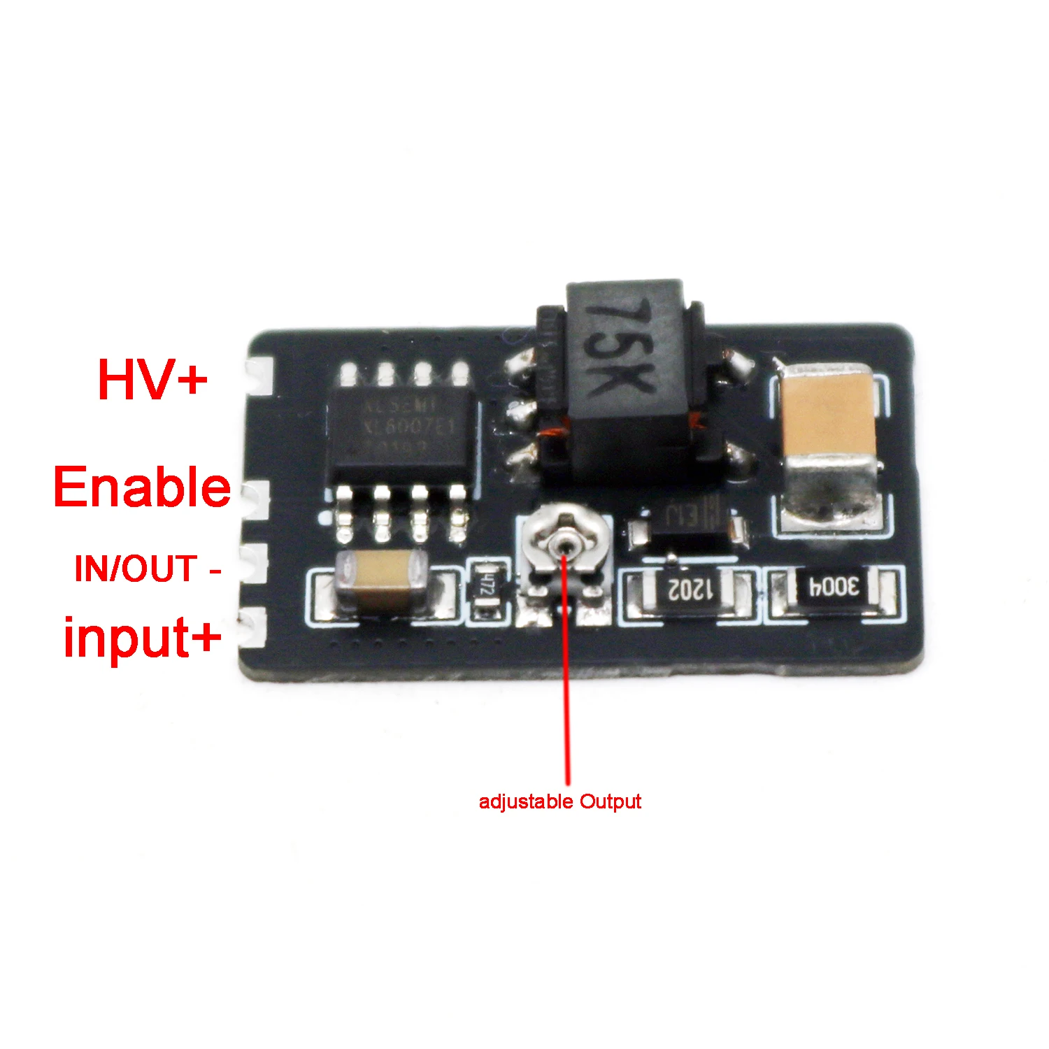
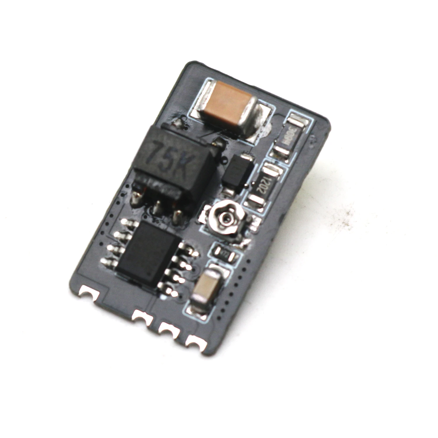
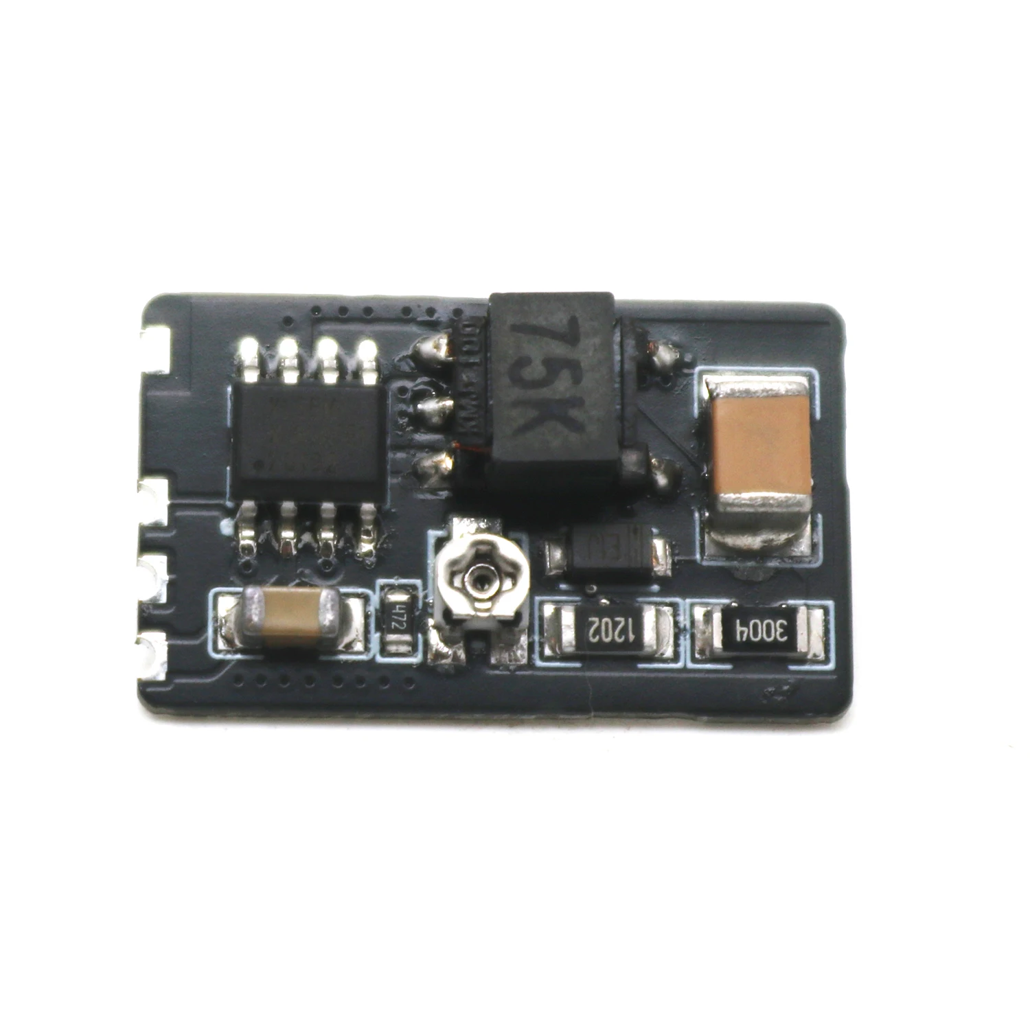
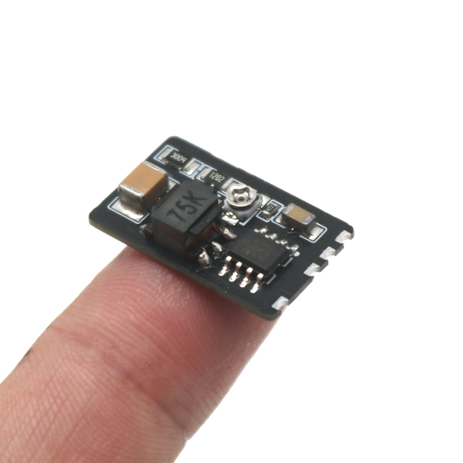
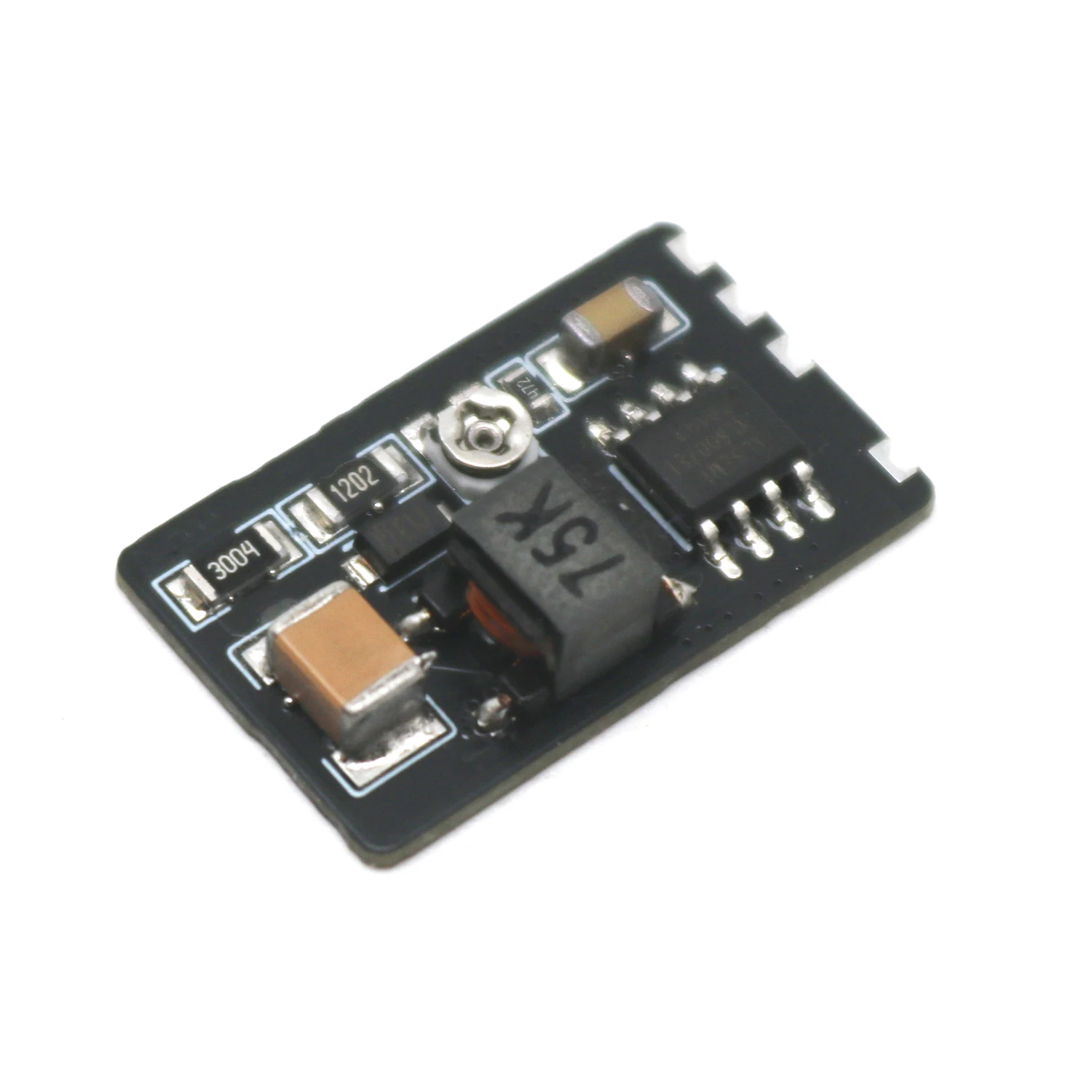
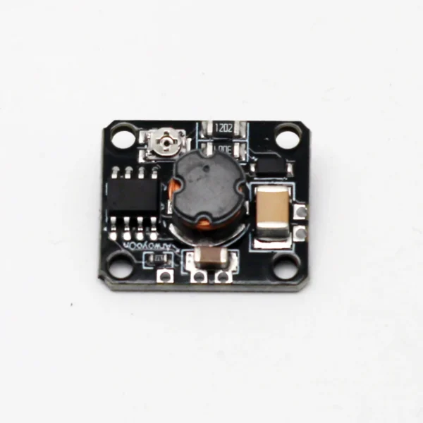
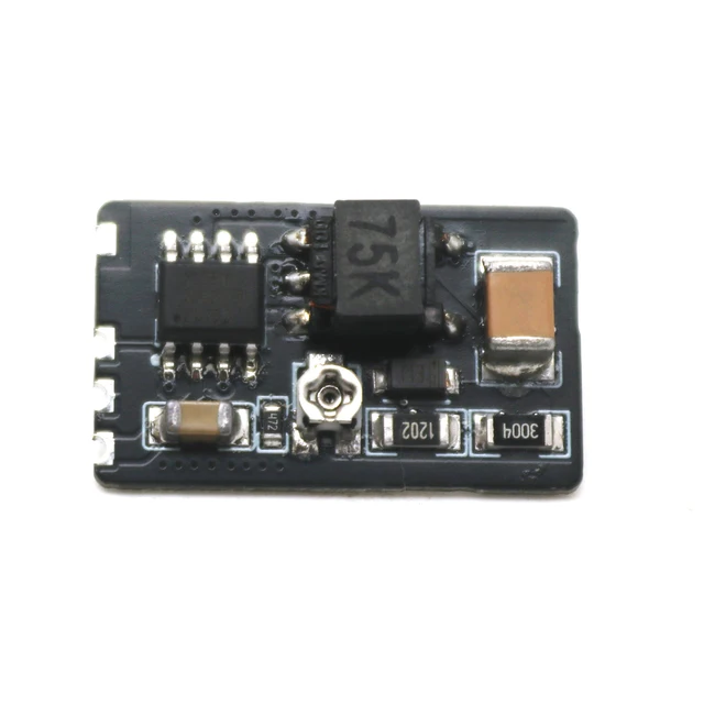
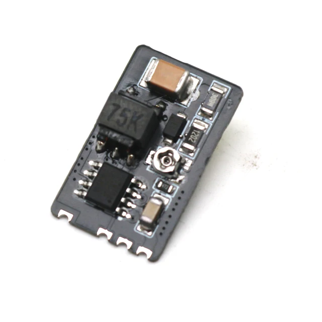
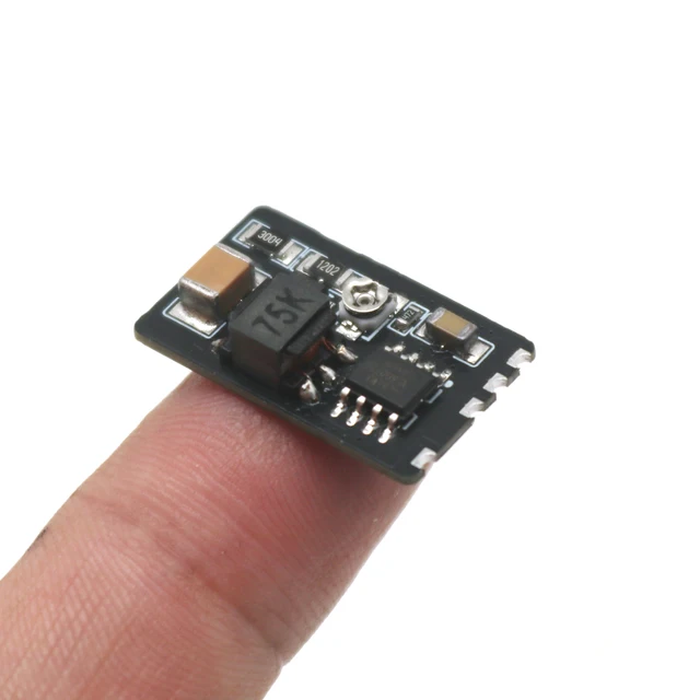
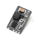
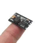
This high-voltage boost converter module is specifically designed to drive Nixie tubes, converting low-voltage DC input (3.3-20V) into adjustable 150-300V high-voltage output. With compact dimensions (23×14mm) and breadboard compatibility, it is ideal for electronic projects like retro clocks.
2. Key Specifications
| Parameter | Value |
| Input Voltage | 3.3-20V DC |
| Output Voltage | Adjustable 150-300V |
| Max. Input Power | 2W |
| Dimensions | 23×14mm |
| Pin Spacing | 2.54mm (Breadboard-friendly) |
| Ground Configuration | Common GND for Input/Output |
3. Pin Definitions
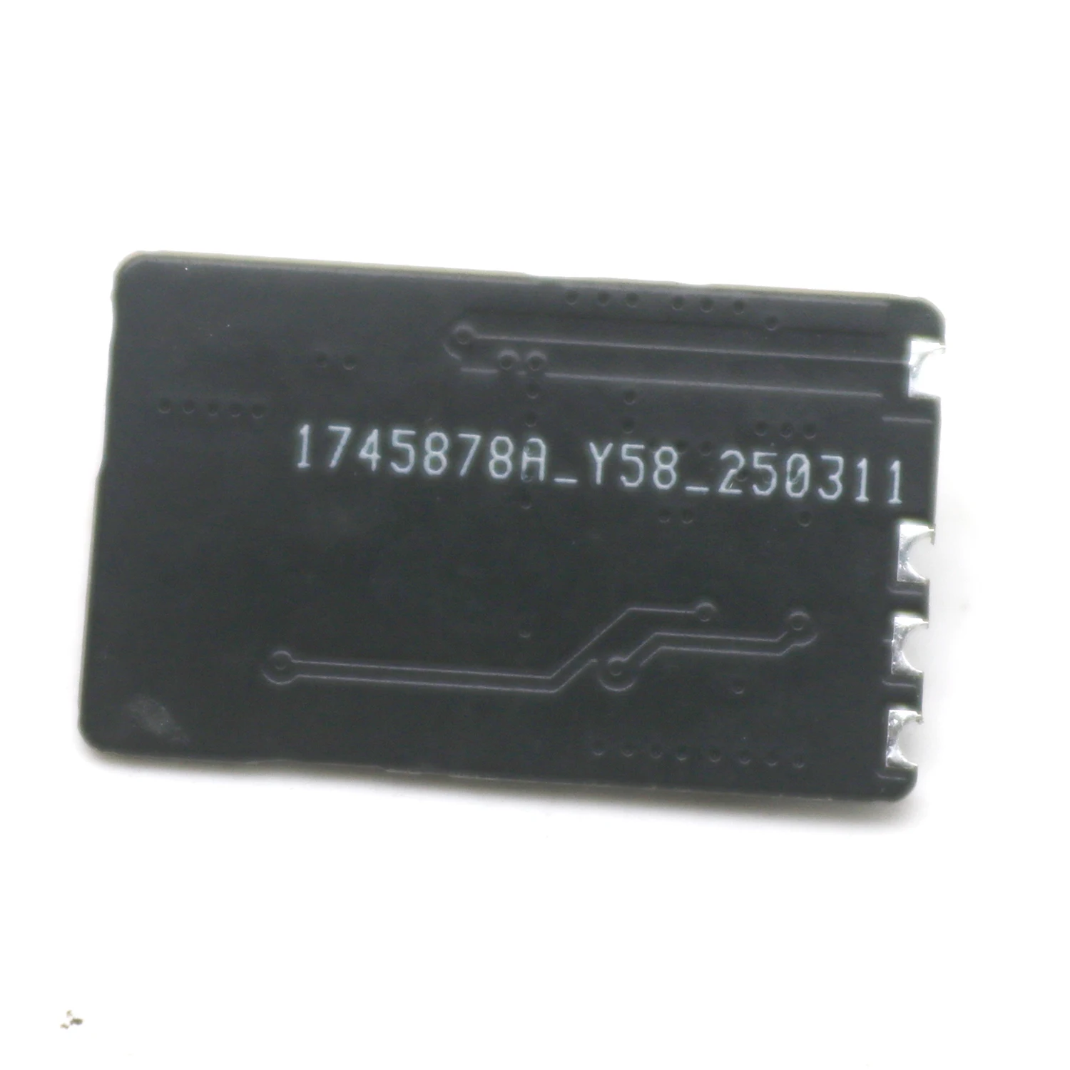
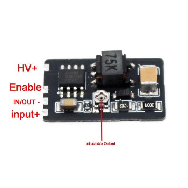
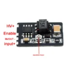
(Refer to actual pin diagram on PCB)
-
VIN: DC Input Positive (3.3-20V)
-
GND: Common Ground (Input/Output)
-
EN: Enable Pin (Active HIGH, pulled LOW by default. Must connect to HIGH to activate.)
-
VOUT: High-Voltage Output Positive (150-300V)
4. Operating Instructions
4.1 Wiring Guide
-
Power Input:
-
Connect DC power source:
VIN(+) to power supply,GND(-) to ground.
-
-
Output Load:
-
Connect Nixie tube anode to
VOUT, cathode toGNDvia current-limiting resistor (10kΩ-100kΩ recommended).
-
-
Enable Control:
-
Drive
ENpin to HIGH (3.3V/5V logic compatible) to enable output. -
Leave floating or connect to LOW to disable.
-
4.2 Output Voltage Adjustment
-
If equipped with voltage adjustment (verify module version), calibrate output by:
a) Using an external potentiometer between designated pins, OR
b) Modifying feedback resistor values (consult technical support for ratios).
5. Critical Safety Notices
⚠️ LETHAL HIGH VOLTAGE WARNING
-
Output exceeds 150V DC! Always power off before wiring.
-
Never touch exposed contacts during operation.
⚡ Electrical Safety
-
DO NOT reverse input polarity or exceed 20V input.
-
Ensure total power <2W (e.g., Max 160mA @12V input).
🌡️ Thermal Management
-
Continuous full-load operation may cause overheating.
-
Maintain ambient temperature <40°C with adequate ventilation.