

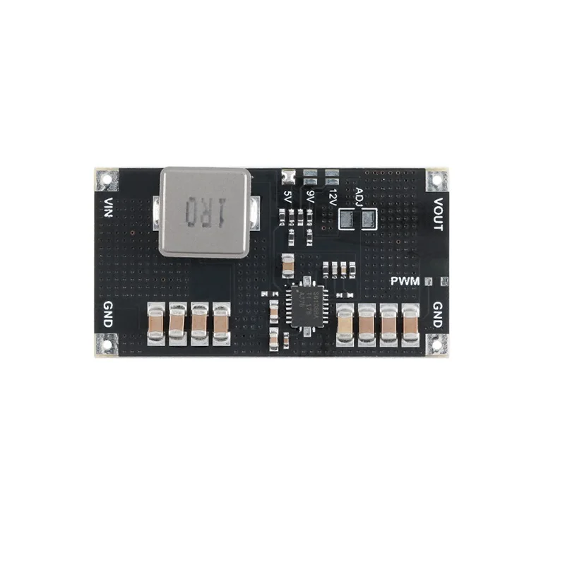
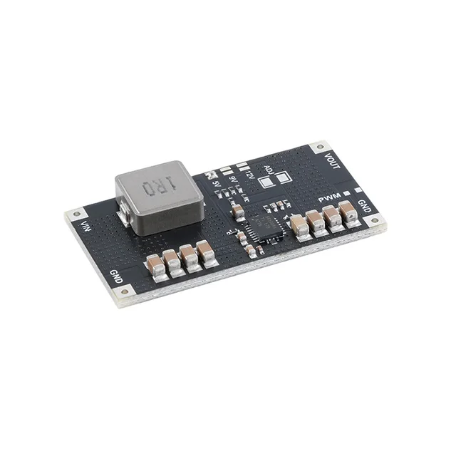
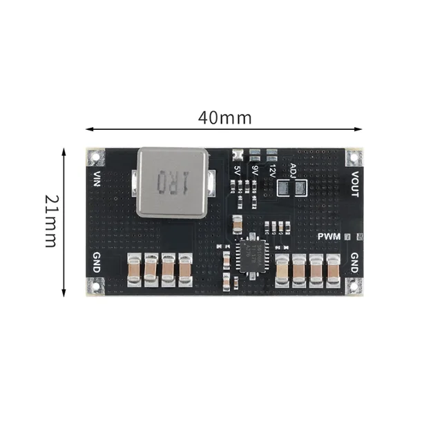
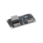
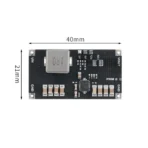

This module uses TITPS61088 power chip programme, stable performance, small ripple, with 10A switching current capability, switching frequency of about 1MHZ, the module provides PWM and PFM two modes of operation can be adjusted by the user (the default PFM low-power mode shipment), on-board high-quality Vantage capacitors (adjustable version) and high-current inductors, the use of high-quality components to further improve the module’s performance and stability.
Module in the output of high-power occasions still have most of the other boost module can not be comparable to the stability of the user in the use of multiple carp batteries in parallel power supply boost applications to 5V voltage 4A/5A output of high-current occasions are a good choice, the same boost to 9V112V voltage is not a problem, the output power Highest up to 30W, 9V, 12V voltage output, the output of larger current occasions, the user can be used in the same way. The user only needs to do a good job of heat dissipation to get a good output ripple with load when the output of larger current occasions.
If not specified, the following parameters are tested in PWM mode (recommended operating mode).
– Module Type: Switching Power Supply, Boost Power Supply
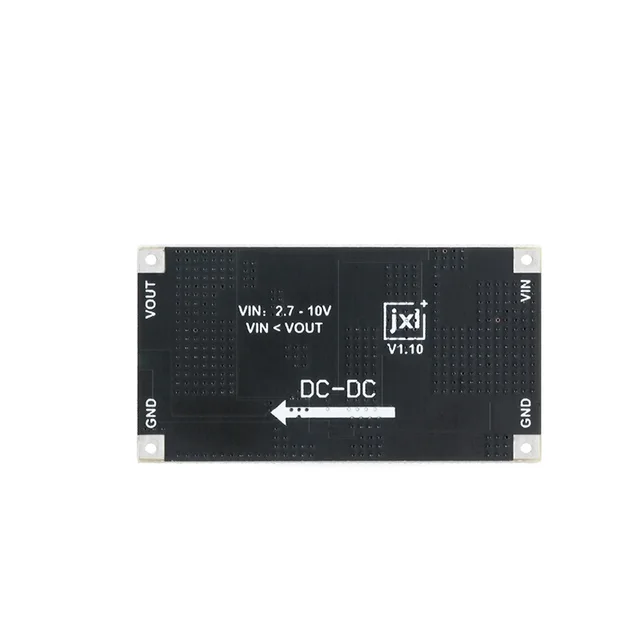
– Input Voltage: DC2.7-12V
– Input Current: 9A(max)
– Output Current: Depends on input, refer to the following instructions for calculation
– Output Voltage: DC4.5-12.6V
– Output power: 30W(max), heat dissipation is required.
– Switching Frequency: Approx. 1MHZ
– Operation Mode: PWM / PFM
– The following parameters are measured when the boost value is adjusted to 9V in PWM mode, for user’s reference.
– Quiescent current: 15-65ma (PWM mode)
200ua-600ua (PFM mode)
– Output ripple: 30mVpp (no load)
– Output efficiency: 92%(max)
– The PWM shorting pads on the side of the output terminals are shorted for PWM mode and disconnected for PFM mode, which is the default mode and can be adjusted by the user.
– For the constant voltage version, the default is PFM mode, which can be adjusted by soldering a 0 ohm resistor to the PWM pads or by shorting the two pads in other ways.
– About the Outputs
– The module is a boost module, so the output voltage needs to be larger than the input voltage. After testing, it is recommended that the output voltage is more than 2V higher than the input voltage, otherwise the output voltage will be higher than the set value.
– The MAX switching current of the module is 10A, and the user is required to leave a margin of 9A or less.
– The output current is determined by the input parameters, and the input current should not exceed 9A. 70% efficiency (leaving a margin) is calculated to obtain the following formula for calculating the module output MAX current value: lout=Vin*6.3/Vout.
– Module in the input voltage is too low when the output power can not be fully played out, in the 3V power supply is particularly obvious, the demand for larger power output users need to pay attention to use.
Cautions
– Please do not touch the bottom potentiometer pin area with your hands or other substances with small resistance value, as the contact will cause the potential resistance value to change and result in large fluctuations in the output voltage.
– Please use shorter/thicker wires for connection when measuring voltage with large current load (wire resistance will affect the measured voltage), or measure directly to the terminals, otherwise the voltage measurement will be inaccurate.
– The above parameters are not the limit value of the module, but rather a certain margin after the parameters specified in the module test its output power in the case of cooling fins for heat dissipation run over 50W, which shows that in high-power occasions a good thermal environment is particularly important.
– About the use of EN port, EN port is connected to VIN by default, for the boost mode on, EN connected to GND for the shutdown mode, users need to note that the shutdown mode does not mean no output, but the chip boost function will be shut down. At this time, the output voltage will be slightly lower than the input and can output current.
– In order to avoid the customer’s hand touching the module circuitry due to static electricity and other reasons leading to chip burnout, so we should try to avoid touching the circuitry near the chip when the module is powered on.


